Wiring diagram for two speed moto explained. Diagram er7 diagram er6 diagram er5 3o wiring diagrams w2 orange brown blue black red grey w2 u2 u2 v2 v2 u1 u1 v1 v1 w1 w1 l1 l1 l2 l2 l3 l3 e e two speed motors high speed low speed orange brown.
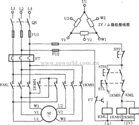
3o wiring diagrams 1o wiring diagrams diagram er9 m 3 1 5 9 3 7 11 low speed high speed u1 v1 w1 w2 u2 v2 tk tk thermal overloads two speed stardelta motor switch m 3 0 10v 20v 415v ac 4 20ma outp uts diagram ic2 m 1 240v ac 0 10v outp ut diagram ic3 m 1 0 10v 4 20ma 240v ac outp uts these diagrams are current at the time of publication.
2 speed motor control wiring diagram. Two speeds two directions tapped wound multispeed 3 phase motor control diagram. Please help how to go about this. Two speed electric motors operate in one of two ways.
Understanding of motor control wiring dia grams. The basic control circuits include two wire three wire controls manual automatic sequential control stopstart forward reverse and jogging circuits. If you are working on two speed motor wiring you will need an ac power supply the two speed motor and a double pole double throw switch.
Like subscribe and dont skip the ads. Two wire control as seen in configuration 1 consists of a control device containing one set of contacts used to facilitate the on an off operation of a pilot device. It has four terminals.
Two separate windings designed to rotate the motor at two different speeds or inbuilt resistors which alter the voltage supplied to windings. However the wiring to the motor is the same. Supply to limit the current if you have made a mistake in the wiring.
Two speed manual motor starter is designed for starting protecting small single phase two. By connecting the proper wires to the high and low speed terminals on the motor and switch you can control how fast or slow it turns once powered up. Most of the diagrams in this book are shown in two ways.
Power and control circuit for 3 phase two speed motor. 2 speeds 2 directions multispeed 3 phase motor power control diagrams abbreviationsol over load relayno normally opennc normally closelow low speedhigh high seed for forwardrev reverse two speeds two directions multispeed 3 phase motor power diagram power diagram. One terminal is the ground another.
There is a wiring diagram and adjacent to it a line diagram. Diagram for motor control stepper motor controller circuit and motor related circuits. Kindly email me the diagrams for star deltor and direct online for a 3speed 1directon 3ph motor have two of them in a bow cutter.
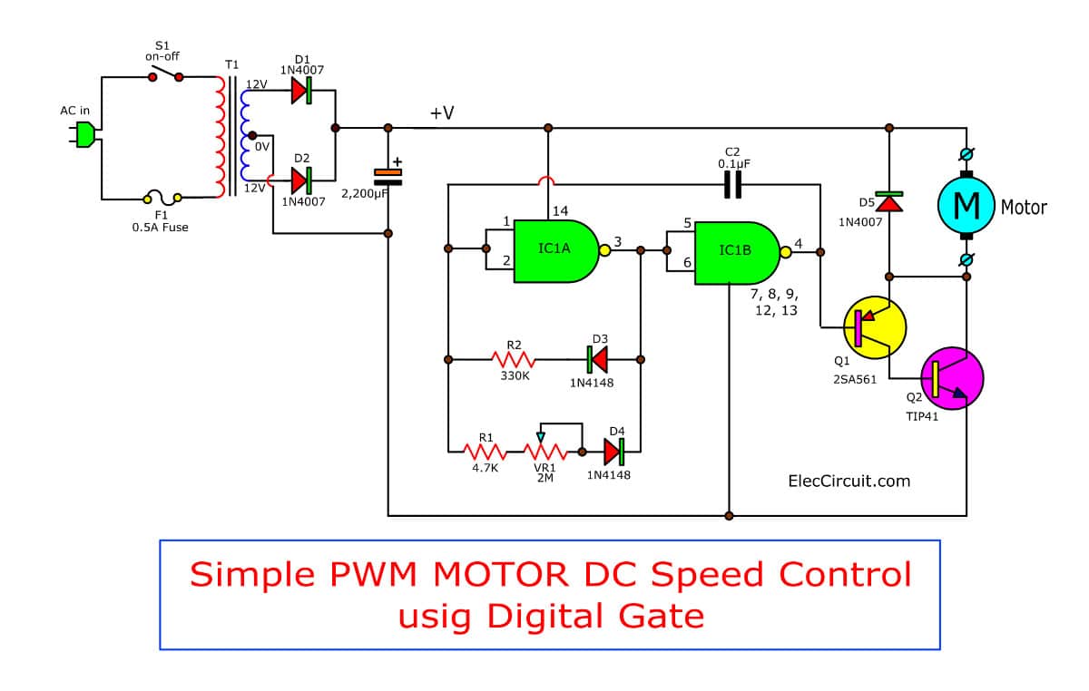
It is important to note. The total current drain is about 25ma with the pot fully off rising to 125ma when fully on. Addition of a power diode for motor speed control although a small.
One contactor burnt for high speed and a replced contactor does not engange originally the coils re fed with a nutural and the one i replaced is only working with a phase. Wiring diagrams external rotor motors n these diagrams are current at the time of publication check the wiring diagram supplied with the motor.


0 Response to "2 Speed Motor Control Wiring Diagram"
Post a Comment